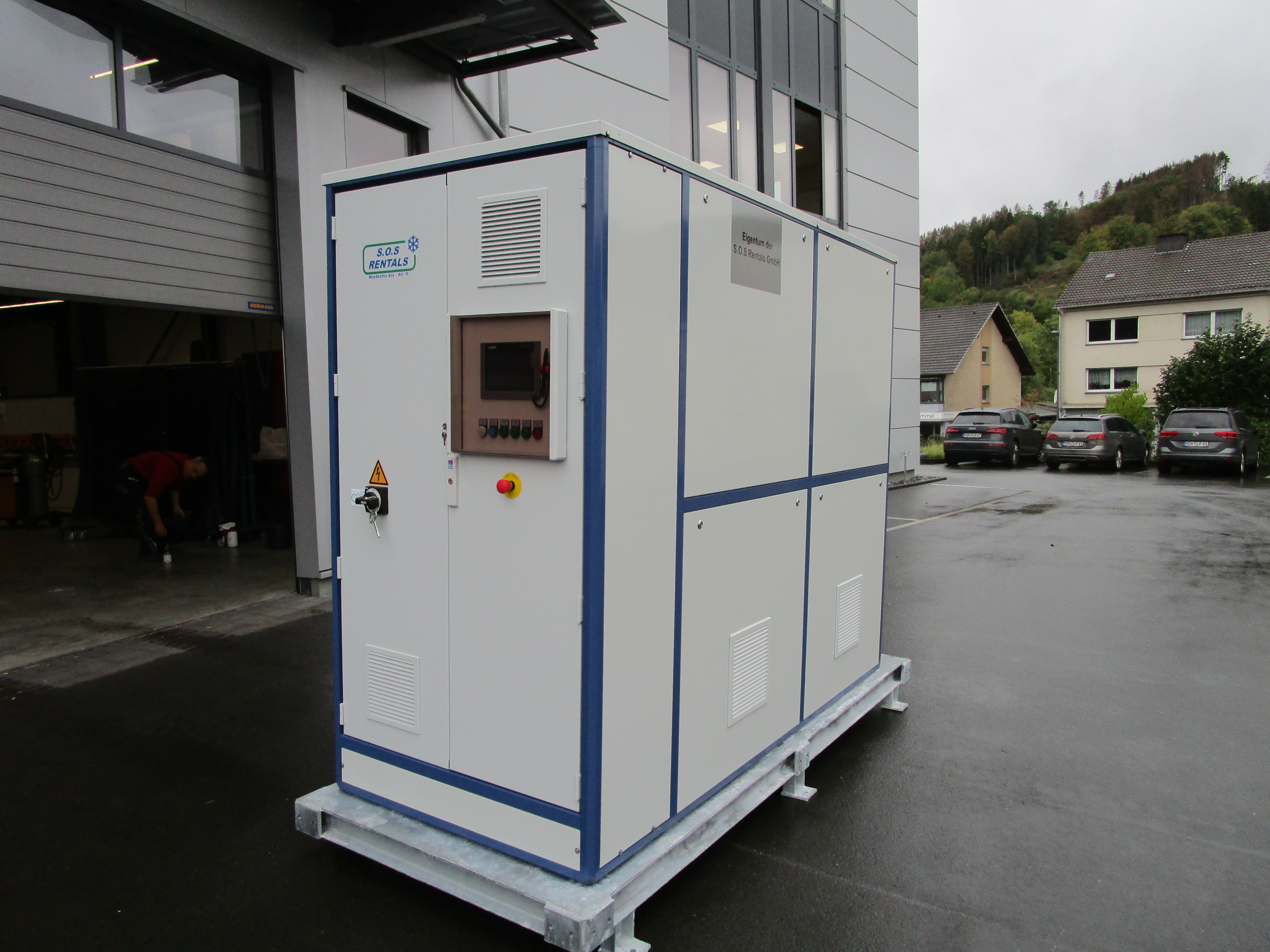
| Electrical data | |
|---|---|
| Supply voltage | 400 V / 50 Hz / 3 Ph |
| Max. current draw | 39 A |
| Power at rated load | 21.5 kW |
| Minimum cable cross-section for 25 m feed | 63 A CEE 5x10 mm² |
| Refrigeration circuit | |
|---|---|
| Refrigerant stage 1 | R449A |
| Refrigerant stage 2 | R23 |
| Number of refrigeration circuits | 2 |
| Consumer circuit | |
|---|---|
| Pump head | 2,0 bar |
| Volume flow | 4,0 |
| Dimensions and weight | |
|---|---|
| Length | 3000 mm |
| Width | 1240 mm |
| Height | 2350 mm |
| Weight | 1800 kg |
| Connections | |
|---|---|
| Consumer | 2x Flansch DN 32 |
| Sound pressure level | |
|---|---|
| at 10 m | 45 dB(A) |
| Operating environment |
|---|
| Max. 35 °C Außentemperatur |
| Coolant |
|---|
| Methanol Ethanol Therminal D12 Fragoltherm F-12 |
| Special equipment |
|---|
| Verbraucherpumpe: FU Regelung |
| Verdichter: FU Regelung |
| Touchpanel: TP 700-TIA V15.1 |
| Fernwartung: UMTS-Router |
| Steuerung: Siemens SPS S7 |
| Brine temperature [°C] |
Compressor stage 2 [°C] |
Condenser stage 2 [°C] |
Compressor stage 1 [°C] |
Capacity control [%] |
Cooling capacity [kW] |
Electrical power [kW] |
Current draw [A] |
Heat output [kW] |
|---|---|---|---|---|---|---|---|---|
| -70 | -75 | -20 | -25 | 100 | 4 | 7 | 10.1 | 11.1 |
| -60 | -65 | -20 | -25 | 100 | 8 | 11.3 | 16.3 | 19.2 |
| -50 | -55 | -20 | -25 | 100 | 9 | 13.7 | 19.8 | 22.4 |
| -45 | - | - | - | - | - | - | - | - |
| -40 | - | - | - | - | - | - | - | - |
| Brine temperature [°C] |
Compressor stage 2 [°C] |
Condenser stage 2 [°C] |
Compressor stage 1 [°C] |
Capacity control [%] |
Cooling capacity [kW] |
Electrical power [kW] |
Current draw [A] |
Heat output [kW] |
|---|---|---|---|---|---|---|---|---|
| -70 | -75 | -20 | -25 | 100 | 4 | 6.1 | 8.9 | 10.2 |
| -60 | -65 | -20 | -25 | 100 | 8 | 9.3 | 13.5 | 17.5 |
| -50 | -55 | -20 | -25 | 100 | 9 | 11.3 | 16.4 | 20.4 |
| -45 | ||||||||
| -40 | -45 | -20 | -25 | 100 | 10 | 13.3 | 19.3 | 23.4 |
| Brine temperature [°C] |
Compressor stage 2 [°C] |
Condenser stage 2 [°C] |
Compressor stage 1 [°C] |
Capacity control [%] |
Cooling capacity [kW] |
Electrical power [kW] |
Current draw [A] |
Heat output [kW] |
|---|---|---|---|---|---|---|---|---|
| -70 | -75 | -20 | -25 | 100 | 4 | 5.5 | 8 | 10.9 |
| -60 | -65 | -20 | -25 | 100 | 8 | 7.5 | 10.9 | 15.9 |
| -50 | -55 | -20 | -25 | 100 | 9 | 9 | 13.1 | 18.1 |
| -45 | - | - | - | - | - | - | - | |
| -40 | -45 | -20 | -25 | 100 | 10 | 10.5 | 15.2 | 20.7 |
The cooling capacity stated above is the net capacity at the evaporator. The heat input into the hydraulic system caused by external pumps and insulation losses must be taken into account.
* Rated operating point